[Revised May 7, 2008]
Hull measurements are not applicable for the fiberglass Cape Cod Bullseye, since the boats are built over and around molds owned and maintained by the Cape Cod Shipbuilding Company ("the Company"). In case of the destruction of said molds by fire, or other cause beyond the control of the Company, the Company has agreed to reproduce the molds, so that the one-design philosophy of the (then) new boats shall remain unchanged relative to the old boats.
No change in the dimensions, location, weight, shape or materials of the keel, rudder, or spars from such dimensions, location, weight, shape and materials which are standard for the Cape Cod Bullseye shall be permitted, except such changes which are incidental to the upkeep of such items.
a. Each racing Bullseye mast must be made from the Zephyr #2 extrusion and be assembled by Zephyr Products, a division of Cape Cod Shipbuilding. The mast head sheave, taper, jib halyard hound assembly, spreaders brackets, spinnaker pole track, sail feed slot and exit boxes must be made and installed by Zephyr. (These are all standard items on new masts and have been with the exception of the spreader brackets.) Spinnaker equipment, wind indicators and flag halyards may be installed by anyone.
b. Each racing Bullseye must be equipped with a mooring cleat located on the foredeck and a bow line chock located on the bow.
c. Each racing Bullseye, whether wet sailed or dry sailed, must have anti-fouling bottom paint covering all areas on the bottom from the water line down.
d. All racing Bullseyes must have rubrails, vinyl on boats built from 1956 to present or fiberglass bumps on boats built in or before 1955
e. All racing Bullseyes must have a wooden (teak or mahogany) toe rail from bow to stern. The toe rail measures 5/8” high by 3/4” wide.
f. For all racing Bullseyes the keel shall remain external as manufactured and may not be encapsulated in epoxy or fiberglass, changing the configuration of the keel or hull.
No change in the locations or dimensions of the standing rigging, which are standard for the Cape Cod Bullseye, shall be permitted except by the vote of the membership. No adjustments to any of the standing rigging shall be made after the start of or during any race, except for emergency and temporary repairs. Spreaders may be utilized. Shrouds may be moved aft six inches from the standard deck attachment positions or returned to the standard deck attachment positions before the start of any race. A spinnaker sheet catcher may be used on the forestay chain plate or forestay turnbuckle not to protrude more than 4” from the bow of the boat. This extension does not change the LOA (Length Over All) of the boat.
a. Running rigging shall be installed at the discretion of the owner and in conformity with Chartered Fleet Standards.
b. Boom vang and tiller extension shall be permitted.
c. No special device, such as hiking straps, to carry weight outside the rail of the boat shall be permitted.
d. No shifting ballast shall be carried.
e. No electrically powered equipment, including electronic instrumentation, is permitted.
Exceptions are allowed for electronic wrist watch timers, electronic compasses (limited to display of time and direction), portable running lights, the use of automatic bilge pumps when a boat is lying unattended at a mooring, and mobile telephones or marine radios used in times of emergency. It is up to the host fleet to use the VHF radio to communicate with competitors from the time they leave the mooring until they get back to the mooring.
The following minimum equipment shall be on board the boat at all times:
a. A 5 lb. Danforth anchor, or its equivalent, 6 feet of 1/4 inch chain and at least 100 feet of 3/8 inch nylon anchor rode;
b. One U.S. Coast Guard approved life jacket of suitable size for each person on board;
c. A paddle or an oar at least 4 feet in length;
d. A horn in working order;
e. A bucket suitable for bailing. In addition, a manual pump may also be carried;
f. A navigational compass in working order.
Note: The current International Sailing Federation (ISAF) "Equipment Rules for Sailing" shall be used as a reference document when questions of definition or measurement methods arise.
Note: A measurer shall not measure any part of a boat owned by himself, or in which he is an interested party, or has a vested interest.
Note: If an official measurer is in any doubt as to the application of, or compliance with, the class rules of any part of a boat he shall consult the National Association or it's representative present at the competition before signing a measurement certificate or attaching a certificate mark. It is not a measurer's job to make rule interpretations.
a. All sails shall be constructed and measured in accordance with the provisions of Article III, Sections 1 through 4.
b. All new, previously unmeasured or recut sails must be measured and marked by an Association approved sail measurer prior to being used for a Nationals competition. All sails previously measured and marked at a Nationals competition may be used in future Nationals competition, if the "mark" is still readable. Competitors must show their "marked" sail to the measuring committee. Article III Section 1-1.1b takes precedence over Article III Sections 2, 3, and 4.
c. All sails must be legibly marked with an indelible marker. The marking shall include the measurement date, the initials of the measurer and the group affiliation (Yacht Club). This marking shall be made at the tack of all sails.
d. All sails shall be measured while dry and lying on a flat surface. All measurements shall be made in a straight line.
e. Boltropes, tapes or wire, where used on the edges of any sail, shall be considered as part of the sail when measuring or determining all dimensions or locations, except as otherwise specified.
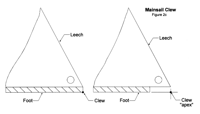
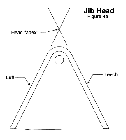
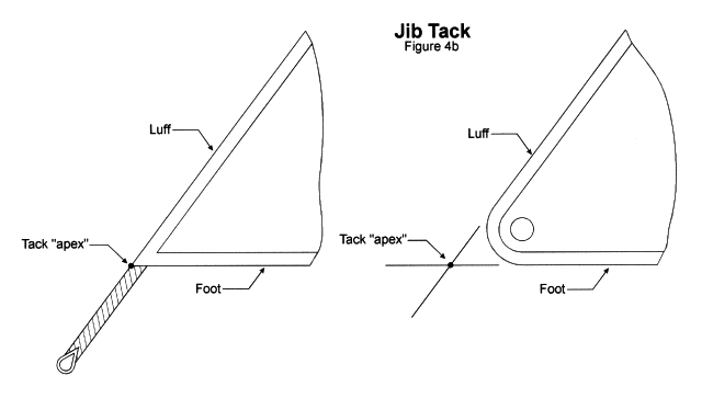
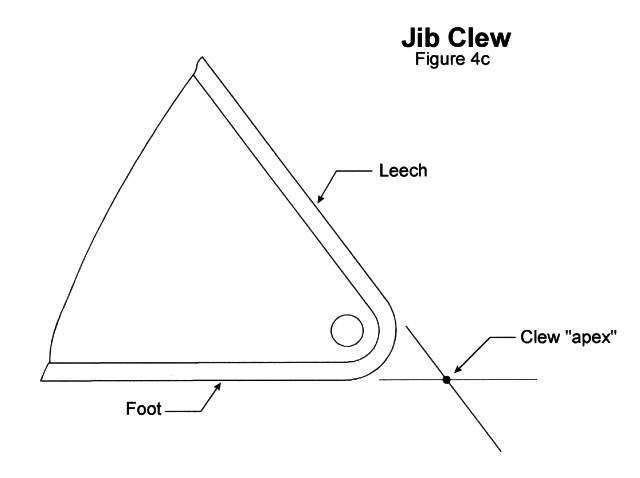
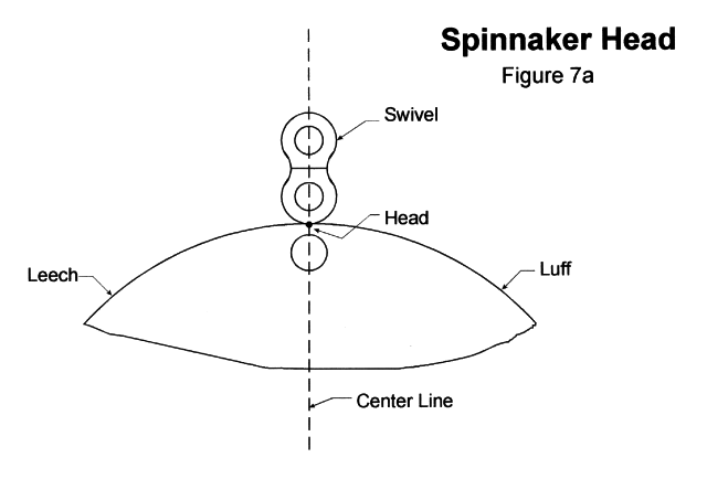
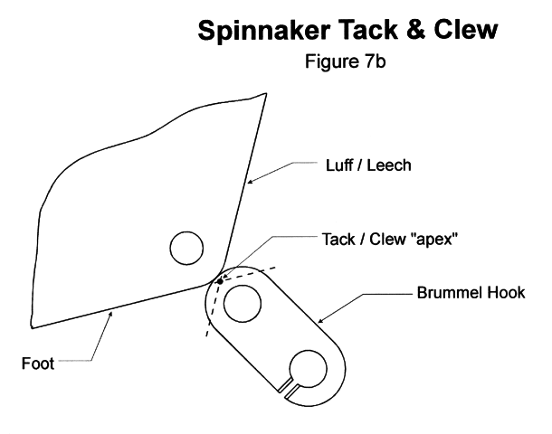
f. To find a corner measurement point or "apex" may require the extension of the line of the edges of the sail adjacent to the point. Where the line of the extension is obvious this should be used. Placing a batten along the edge can often help to give a true extension line continuing any curve. Where the line of the extension of the edge is uncertain and not repeatable leading to inconsistent measurements points, the measurement of the sail should be refused. Cringles, thimbles, or other hardware, which are partly or entirely external to the sail shall be disregarded. (Refer to Figures 4a, 4b, 4c, 7a, and 7b)
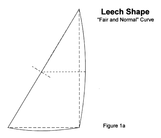
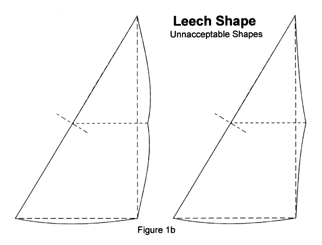
g. The leech of the jib and of mainsail may be of any shape, except that no part of the sail be so constructed as would be deemed or might be deemed by a measurer to be a violation of the intent of Article III, Section 2.f. (girth restrictions). The leech shall be a "fair" and "normal" curve particularly along its midpoint. Refer to Figures 1a and 1b.

h. If a sail measures outside the published specifications the measurer shall show the owner the reason for the discrepancy and recheck the sail with the owner present.
i. Any quantity of sails may be measured for competition, however only two spinnakers, one mainsail, one genoa jib and one working jib shall be allowed on board on any given day of a Nationals Competition.
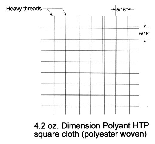
a. Permitted: One ply of woven cloth e.g., cotton, Dacron, or polyester.
Example; use of 4.2 oz Dimension Polyant HTP® square cloth is permitted. This is a woven material much like rip-stop spinnaker cloth except heavier and stiffer.
b. Not permitted: Laminated sail material, film, Mylar, Kevlar, tri-axial construction or other variations of materials. Two or more plys are not permitted except when used as reinforcements as described below in Article III, Section 1.3.
Reinforcements at the corners of the sails, made only of permitted types of woven fabrics, for the purpose of ensuring the integrity of the sail and the longevity of the original sail shape, may be of two types; "Stiffening" and "Additional". Such reinforcements are to be measured from the actual physical corner of the sail, not from an extended "apex" or "triangulation" point. The dimensions given in "a." and "b." below are maximum dimensions. The use of maximum reinforcements is optional and not necessarily recommended.
a. Stiffening reinforcements, constructed of multiple layers of permitted types of fabrics, with or without close stitching, provided that they are within a 24 inch maximum radius from any corner of the sail, are permitted.
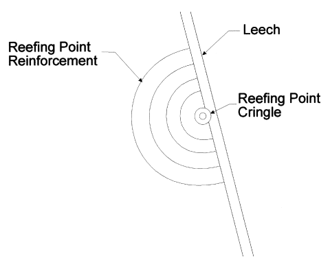
b. Additional reinforcements, which are a continuation or an extension of the corner stiffening area, constructed of not more than two layers of permitted type of fabrics, of the same weight or lighter weight as the body of the sail, are permitted. Additional reinforcements must be flexible, must be capable of being folded in any direction and must not exceed a maximum radius of 72 inches from any corner of the sail. Any form of stiffening, including additional reinforcements, the use of bonding agents, and close stitching, is prohibited at the tack of the mainsails or jibs. Glued seams shall not be considered a form of stiffening if they can be folded in any direction.
c. Additional reinforcement at a reefing point cringle is permitted.
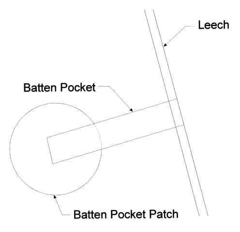
d. Circular batten patches to reinforce the inner end of batten pocket is permitted. This may be made from 2 oz. insignia cloth with adhesive or from heavier cloth and sewn in.
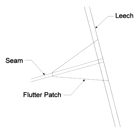
e. Flutter patch covers at seam to reinforce the sail edge are permitted. This lessens "comb-out" of the seam and greatly reduces the chance of seam failure at the leech.
a. Boltropes and tapes may be of polyester or nylon. Normal tabling is permitted provided that the sail is not stiffened by the tabling.
b. Battens may be constructed of wood or plastic. Wood and plastic battens may be used simultaneously in one sail. Batten pockets shall be no longer than required to accommodate the batten.
c. Telltale windows are permitted in jibs and mainsails. No more than three telltale windows may be placed in any one sail and each telltale window shall not exceed 30 square inches in area.
d. Anti-collision windows, other than telltale windows, shall be permitted in mainsails, genoas and working jibs. Anti-collision windows, where permitted, shall be optional and shall be no larger then 2 square feet per sail. Anti-collision windows shall not be placed closer than 6 inches to the luff, leech or foot. Refer to Article III, Sections 2.g. and 3.e.
e. Loose footed mainsails are not permitted.
f. No means of changing size or shape of any sail mechanically, except for roller-reefing or reefing points on the mainsail, is permitted. This shall not restrict the adjustment of tension on the luff or foot by the use of halyards, downhauls, outhauls, cunninghams, or vangs.
g. Any detail of sail construction not expressly addressed in these specifications (e.g., seam direction, width of panels, or type of weave) is allowed.
h. The use of leech lines in all sails is permitted to reduce flutter after aging and stretching.
Note: Boltropes, tapes or wire, where used on the edges of any sail, shall be considered as part of the sail when measuring or determining all dimensions or locations, except as otherwise specified.
Tackless Mainsails which were cut and delivered between June 1990 and April 22, 1999 with a maximum Girth measurement of 6 feet 3 inches shall be accepted for competition in Nationals competition.
All new or recut mainsails delivered after April 22, 1999 shall comply with the new dimensions and measurement methods outlined in the Bullseye Technical Specifications as revised in April of 1999.
There will be no requirement for special marking of masts or booms. All spars are manufactured by Zephyr Spars which is a division of Cape Cod Shipbuilding. These spars are manufactured to a set of standard specifications which are regulated by Article IV of the Bullseye Class Association - Constitution and Bylaws and Article I, Section 2 and Article II, Section 1 of the Bullseye Class Association - Technical Specifications. The use of Cunninghams will be allowed, as long as they are not hydraulic in design. Traditional block and tackle designs are permitted.
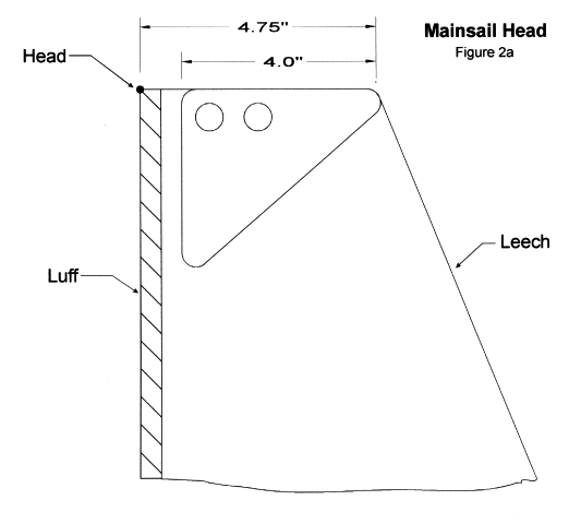
a. The headboard may be of plastic, cast or flat metal and shall not be more than 4 inches wide when measured across the top of the headboard perpendicular to the luff, and not more than 4.75 inches wide when measured across the top of the headboard from the outer edge of the luff, including the boltrope, to the outer edge of the leech. Refer to figure 2a.
b. The mainsail shall contain three battens spaced approximately equally along the leech. The upper batten shall not exceed 15 inches, the middle batten shall not exceed 24 inches, and the lower batten shall not exceed 21 inches.
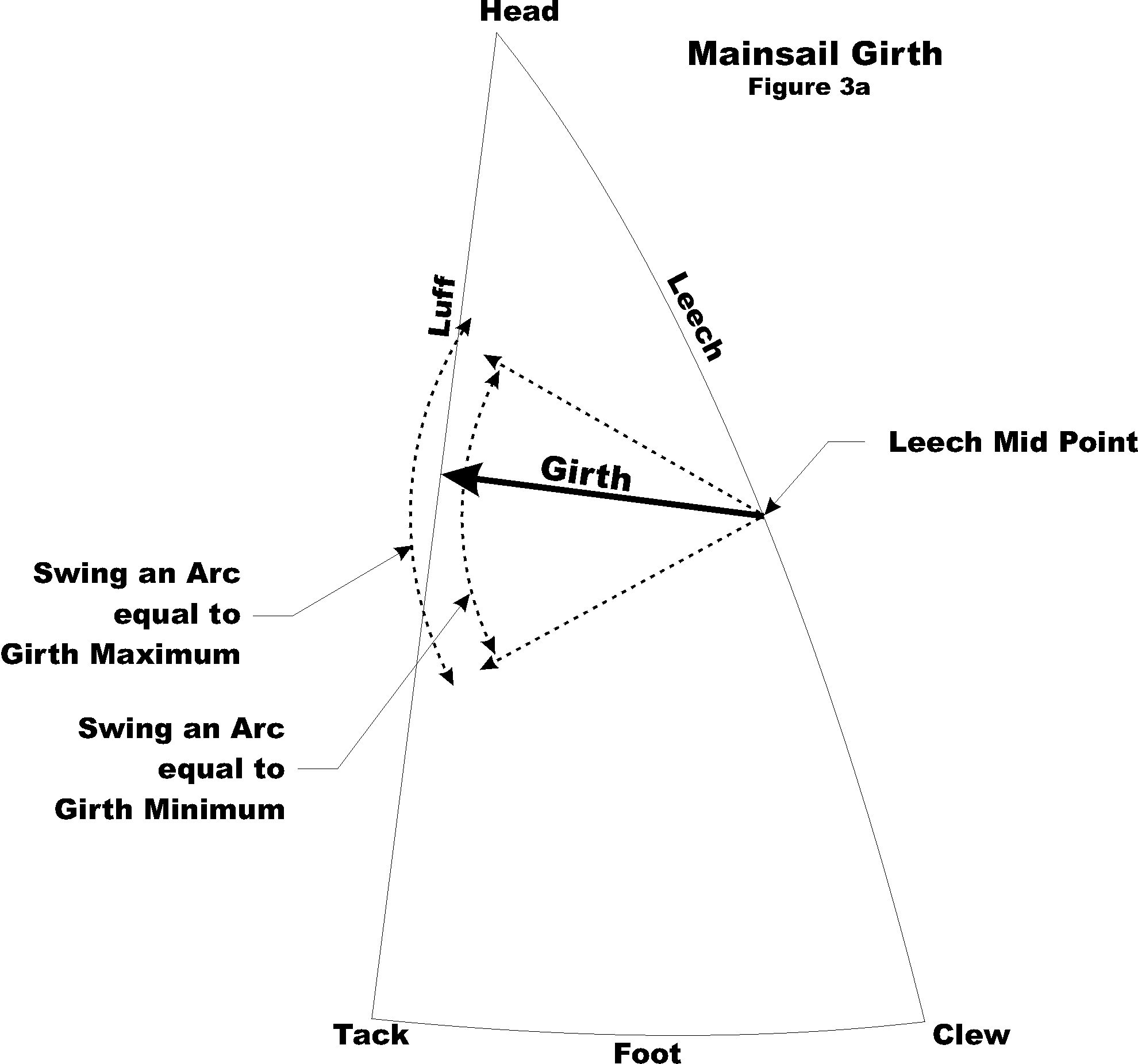
c. The leech of the mainsail shall be measured, with battens removed, under a pull of 10 lbs. applied at the clew thimble with the headboard fixed as a stationary point. Refer to figures 2a, 2c and 3a. The straight line measurement shall be taken from the apex of the headboard at the luff edge, including the boltrope, to the apex of the foot at the clew, including the boltrope. This measurement shall not exceed the following limits:
| Maximum | Minimum |
|---|---|
| 20' 3" (243") | 19' 9" (237") |
d. The girth of the mainsail shall be measured, without tension, as the shortest straight line distance swung across the sail by a tape from the half leech point to the luff including the bolt rope . The half leech point is found by folding the head point to the clew point and equally tensioning the two halves of the leech so formed. The half leech point is the intersection of the fold and the leech. The measurement shall be taken with the sail smoothed without pulling or stretching the cloth on the bias. The measurement shall not exceed the following limits:
| Maximum | Minimum |
|---|---|
| 6' 1" (73") | 5' 10" (70") |
e. The use and location of mainsail anti-collision window(s) shall be optional. If used, the total area shall be no larger than 2 square feet per sail and not placed closer than 6 inches to the luff, leech or foot.
Figures 2b and 3 are no longer used.
a. No headboards are permitted on any jib.
b. Two battens (optional) may be used in the working jib spaced approximately equally along the leech. They shall not exceed 12 inches each. No battens are permitted in the genoa jib.
c. To measure both the working jib and genoa:
| Maximum | Minimum | |
|---|---|---|
| Luff | 14' 2" (170") | 13' 10" (166") |
| Leech | 12' 5" (149") | 12' 1" (145") |
| Foot | 4' 10" (58") | 4' 8" (56") |
| Girth | 2' 9" (33") | 2' 7" (31") |
| Maximum | Minimum | |
|---|---|---|
| Luff | 14' 6" (174") | 14' 2" (170") |
| Leech | 13' 10" (166") | 13' 6" (162") |
| Foot | 8' 6" (102") | 8' 4" (100") |
| Girth | 4' 3" (51") | 3' 11" (47") |
NOTE: On the girth measurement, be sure to use the head apex when matching up to the tack and clew. Do not measure cringle to cringle as this will incorrectly increase your girth measurement. Refer to the drawings below.
d. A jib club, conforming to Cape Cod Shipbuilding specifications, shall be mandatory for use with the working jib.
e. The use and location of a genoa or working jib anti-collision window shall be optional. If used, the total area shall be no larger than 2 square feet per sail and not placed closer than 6 inches to the luff, leech or foot.
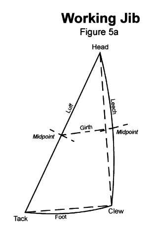
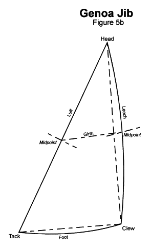
a. No headboards shall be permitted.
b. The spinnaker must be measured on a clean dry area large enough to allow for the entire length of the sail and one-half of the width of the sail to be laid out.
c. The sail shall be folded in half around a vertical axis by placing the luffs/leeches together with the body of the sail pulled out to one side. Refer to figure 6.
d. The luff and leech shall be measured from a point on the edge of the sail at the center of the head cringle to the "apex" or "triangulation" of the tack and clew. Refer to figures 7a, 7b and Article III, Section 1.1.f. Both the luff and leech shall be measured simultaneously with 10 lbs. of tension applied to the tack/clew with the head fixed as a stationary point. This measurement shall not exceed the following limits:
| Maximum | Minimum |
|---|---|
| 17' 2" (206") | 15' 6" (186") |
e. The spinnaker maximum width shall be the maximum width, whether at the foot or across the body of the sail, between points on the luff and leech equidistant from the head. Beginning at the top of the sail and working down to and including the foot of the sail, a series of half girths must be measured at close intervals.
The half girth is measured by placing the zero end of a tape measure at the leeches/luffs and measuring across the sail to the fold line. An arc must be swung from the leeches/luffs to locate the perpendicular from the fold line. In any one station, the perpendicular is the shortest distance between the luff/leech edges and the fold line or the smallest measured distance. Refer to figure 6. The largest half girth when doubled is the Spinnaker Maximum Width.
NOTE: When measuring the girth be careful not to put any tension on the cloth. It should only be smoothed out to remove wrinkles.
| Maximum | Minimum | |
|---|---|---|
| Spinnaker "Max Width" | 12' 0: (144") | 11' 6: (138") |
| Half Girth | 6' 0: (72") | 5' 9" (69") |

f.
The spinnaker pole shall not be more than 6' 9" (81") in overall length including fittings. It shall be permissible to allow the spinnaker guy to run freely through the fitting on the end of the pole. Allowing the spinnaker to fly temporarily away from the pole, either by intention or accident when setting, jibing, or lowering the spinnaker shall not be grounds for disqualification. At all other times the spinnaker must be trimmed in accordance with Rule 50.2 of the I.S.A.F. The spinnaker pole may be used as a whisker pole and one end must be seated against the mast.These pages designed and maintained by the Bullseye Association • Copyright 1997 - 2008